So my plan for bi-weekly video updates failed somewhat.
No surprise there really, even thou I've thought about what to record I've just not been up for the task.
What I have done on the other hand is creating a new development environment using an old spare laptop (is to be used for the CNC - whenever that's done). But I noticed a lot of curious internal compiler errors popping up. At first I thought it was a flawed harddrive or RAM, but it turns out the project is just to complex to properly compile using all optimizations on the limited RAM available on the laptop. GCC has a lot of options to limit memory usage so the problem was quite easily remidied once the cause was known.
With that sorted out I created a debug mode where I can directly toggle switches, lights and solenoids from the laptop. Should ease troubleshooting as some of the switches are reaaaally hard to trigger manually, not to mention specific modes could be a pain to recreate etc.
Now I'd just send (via console) "s5 s6 s7" to toggle switches 5,6 and 7 for instance.
Obviously this would only be useful for momentary switches, but anyway - still very useful.
I also noticed that I forgot to actually upload the music and sound effects to the SD cards (doh!) so that has been done, as well as creating the maintenance diagnostics page for sound and music. While creating the SD cards I noticed one of the major drawbacks of using a Mac - unnecessary hidden folders. That means file #1 wasn't always the first file on the system, so the cards behaved differently in the MP3 Trigger boards. At first, the two sound effects cards looked the same, but showing hidden files it was obvious Spotlight had been indexing files on one of the cards. One of the downsides of programming/handling old filesystems on modern systems, I guess.
Off topic -
I found my pinball machine "featured" in an online quiz as "question #59 (ultra hard) - What's the name of this game?". After numerous guesses such as F-14 TomCat, Addams Family, somebody (who wasn't me!) finally guessed the right answer - my BioShock machine. Fun stuff! :)
Monday, December 9, 2013
Monday, November 18, 2013
Bits and Bytes
Finally an update.
Time is really not my ally these days and since the last post I've not been able to do very much on the machine. I've been busy scheduling gigs for my band, arranging with pressing and distribution of our record, video and photo shoots and a whole lot more. Phew.
But yesterday I got to sit down a program a little and it felt good!
I've decided on a code structure now and will enable feature by feature, ranging from easiest to implement and up. Basic functionality first and then more complex behaviors as needed.
I will program it all using placeholder video and replace the videos as I go, but video has the lowest priority right now and is easily changed when needed. With this approach it's easy to break down each section of the board and independently program it, so the whole task becomes less daunting. In theory, at least.
I have only programmed a couple of basic tasks at the moment, but it's very important that the code is solid, since it should function independently and without human interaction so heavy testing will be required for each mode implemented, whenever a mode is changed etc. But it will be worth it!
Thursday, September 19, 2013
It's...something!
Finally got some time to do a little tinkering on the machine!
The transport section between left ramp and top VUK is now in place.
The idea was to use a plastic transport, since I wasn't able to fix the metal version properly...but the fix was amazingly simple.
I simply fastened a plastic extender from the end of the section and the rest just fell in place.
Feels really nice to finally have this section finished - plastic covers and all!
I also added an extra flasher, since the plastic part was covering up the red light below. I think it both looks better and will probably function better this way as well.
Mr Bubbles got his arm hot glued on and seems to be holding up just fine. Will see how he holds up during a couple of "games". If the arm falls of he'll need some elbow screws...
I also finalized the top right section of the VUK, so that it's bolted in place. Maintenance will be cumbersome, but hopefully won't be needed that often.
I have a couple of things left to do, such as fixing the broken magnet, but no show stoppers and with these additions I can focus on the programming of the actual game itself. Awesome!
The transport section between left ramp and top VUK is now in place.
The idea was to use a plastic transport, since I wasn't able to fix the metal version properly...but the fix was amazingly simple.
I simply fastened a plastic extender from the end of the section and the rest just fell in place.
Feels really nice to finally have this section finished - plastic covers and all!
 |
| 1) Close up of the top left section. |
Mr Bubbles got his arm hot glued on and seems to be holding up just fine. Will see how he holds up during a couple of "games". If the arm falls of he'll need some elbow screws...
I also finalized the top right section of the VUK, so that it's bolted in place. Maintenance will be cumbersome, but hopefully won't be needed that often.
I have a couple of things left to do, such as fixing the broken magnet, but no show stoppers and with these additions I can focus on the programming of the actual game itself. Awesome!
Tuesday, September 17, 2013
The Punk's Not Dead!
I'm still around.
Just a little too much going on right now including album recording and concerts with my band.
So there's been to little time to do anything on the machine.
But soon!
Just a little too much going on right now including album recording and concerts with my band.
So there's been to little time to do anything on the machine.
But soon!
Friday, August 2, 2013
Sisterpage...
I'm starting a new blog for the CNC build - check it out at Poor Man's CNC!
It won't happen a lot until the pinball machine is completed but I figure it's always good to be one step ahead.
It won't happen a lot until the pinball machine is completed but I figure it's always good to be one step ahead.
Saturday, July 27, 2013
Brain transplant successful!
Yeah!
Got my Chipkit replacement today!
I noticed a small difference between the old and new board -
I guess I wasn't the only one having problems with the USB port, right?
So...
I moved all the cables into their correct position, burnt the firmware onto the new card, booted the machine and this happened...
 Doh!
Doh!
What had happened was that I've accidentally swapped the start button with the motor pin, so the motor revved up to about fifty million RPM and due to not being perfectly aligned (kinda causing a rumble effect actually) it tore the arm off.
It's a good thing actually - now I know that super glue wasn't enough and I'll need to put a screw in there as well. Glad it happened now and not under the glass!
Once that was fixed I was back on track!
Oh, I even got hardware status feedback from the soundboards after a firmware update and some soldering - and it's awesome!
Previously the only feedback would be a single message being sent over the serial port which could easily been missed. Now I'll just pull the actual status whenever, wherever.
Today was a good day!
Got my Chipkit replacement today!
 |
| 1) A larger than usual box made me suspicious... |
 |
| 2) Ah! There's my little box! |
I noticed a small difference between the old and new board -
I guess I wasn't the only one having problems with the USB port, right?
 |
| 3) Factory-applied hot glue on the USB port! Note the perfectly aligned USB port (not!) as well... |
So...
I moved all the cables into their correct position, burnt the firmware onto the new card, booted the machine and this happened...

What had happened was that I've accidentally swapped the start button with the motor pin, so the motor revved up to about fifty million RPM and due to not being perfectly aligned (kinda causing a rumble effect actually) it tore the arm off.
It's a good thing actually - now I know that super glue wasn't enough and I'll need to put a screw in there as well. Glad it happened now and not under the glass!
Once that was fixed I was back on track!
Oh, I even got hardware status feedback from the soundboards after a firmware update and some soldering - and it's awesome!
Previously the only feedback would be a single message being sent over the serial port which could easily been missed. Now I'll just pull the actual status whenever, wherever.
Today was a good day!
Wednesday, July 24, 2013
Status update!
All right.
So far I've got everything but the plastic transport from ramp-to-VUK in place, including servos, motors, lights, switches and solenoids. Meaning, I've more or less finished the machine.
What I didn't expect (well, should have...) was that my crappy soldering of the Chipkit USB port would come loose, so now I can't program the board. I'm rather fed up with it so I'll just order a new Chipkit Max32, move wire by wire to the new board and hopefully don't break anything else in the process.
Before moving the USB cable, and ultimately breaking the port, I managed to get the servos and motor up and running in code, as well as the accompanying diagnostics menu for them.
Here's some videos for a change!
Fantastic!
In the videos everything just goes on/off in an instant. The final version of the code will of course feature speed control and less jerky, smoother movements. The idle light sequences are just placeholders as well (i.e random lamp lights up) and will obviously be replaced when the new board is up and running.
I've also noticed that the magnet doesn't work anymore, and by measuring the port it would seem that the port is indeed broken (regardless what I've previously said...)
So, up next is:
1) Making the transport section. Don't know why I've not done this part already...
2) Checking the magnet driver port. The port is broken, will order a new board for this unless repairable.
3) Order and replace the Chipkit.
4) Beautify the playfield - attach top plastic overlays. Not critical and might be skipped completely, actually.
5) Tilt blobbin'. Also optional. We'll see about this.
Then - I can finally start coding the ruleset!
Monday, July 22, 2013
Lightbringer!
Organizing lights and creating/arranging groups, schematics and color schemes is almost as tedious as the light board soldering was. Phew.
But at least things are moving along!
But at least things are moving along!
Friday, July 19, 2013
One down...
Added a power relay to keep playfield power off when booting and when doing maintenance. Reused my old relay board, which finally became useful. And I only broke a single light doing so!
P.s
Not really broken, just under maintenance.

P.s
Not really broken, just under maintenance.

Sunday, July 7, 2013
Holy smokes, Batman!
Got use for my fuse-box in the pinball the other day...
 Yes, I know I should not be doing stuff on the machine while it's on and active.
Yes, I know I should turn it off before disconnecting wires or reconnecting them.
Despite this I always manage to break something by doing just that...
This time the fuses took the hit and saved me from burning most of my electronics. It's rated at 8A so imagine what damage could have been caused if that would have passed through the Chipkit instead.
Yikes.
Thursday, July 4, 2013
Backtrack...Back on Track, I mean!
Great success!
Did a little voodoo-soldering last night and got the switchboard up and running again. The error was pretty easy to narrow down...
Once the IC was replaced I noticed that the current had rippled through the ones following the damaged one, so they needed to be replaced as well. After that - all is good!
I also noticed that the loose cable was indeed VERY loose. Two solenoids had basically no connection at all - which in turn explains why the left bumper mysteriously stopped working. Three times have I replaced the "broken" MOSFET (doh!)...
From the top of my head, following things remain to be fixed until the hardware is finished:
 |
| 1) Spot the error... Yeah, it's that one. |
Once the IC was replaced I noticed that the current had rippled through the ones following the damaged one, so they needed to be replaced as well. After that - all is good!
I also noticed that the loose cable was indeed VERY loose. Two solenoids had basically no connection at all - which in turn explains why the left bumper mysteriously stopped working. Three times have I replaced the "broken" MOSFET (doh!)...
From the top of my head, following things remain to be fixed until the hardware is finished:
- Passage between the left ramp and top VUK. The design is made (will be clear plastic instead of metal) and a cardboard prototype has been created. All that's left is to recreate it in plastic.
- Connect flashers and GI to +12V.
- Add a power relay to keep the lights off while the machine is booting (could possibly blow a fuse). It's possible to modify the lightboard to let the Chipkit keep the signal low, but it's easier this way and way more accessible.
- Adjust a few of the switches. Some of them gets stuck in the closed position and needs a little tinkering to open/close properly. Most notably the center VUK and shooter lane.
- Add a switch for the upper level drophole (can't believe I missed this). It's possible to work around this in the rules, but that would mean the RAPTURE-mode is not possible to handle during multiball.
- Connect the center VUK rail with the right ramp. Just a nut and bolt - easy as pie.
- Connect the servos- and motorcable from the playfield to the cable from the motherboard.
- Attach the plastic overlays above the orbit lane. Need some customization there, but nothing big.
- Enable the service buttons and tilt-blob (optional, can be done with the cabinet closed).
I should say - "finished"- as there is probably going to be a little tweaking here and there, but I will be able to start the actual GAME programming pretty soon!
 |
| 2) Lit and almost fully functional playfield! |
Two thumbs up!
Monday, July 1, 2013
Let there be lights!
After around two years in the making - this is a most welcome sight!
 |
| 1) Most lights active. Global illumination lights are mostly absent in this picture. The final version will be a bit more brighter. |
 |
| 2) View from the underside. |
A little more to do on lighting before calling it done, such as - global illumination, reversing the polarity of two of the bumper lights and some general adjustments.
But it's looking rather good!
Sunday, June 30, 2013
Son of a...
I'm pretty sure either the machine is jinxed, or I am.
Was doing a quick adjustment and fried the entire row of switches on the right side of the playfield.
Joy to the world.
The worst part is - I've done this two times before!
"I better turn of the power this time!", and so I did. Did a quick fix and turned the power back on, realized I needed to do another quick fix and BOOM. Short circuit.
I guess I should be thankful the switchboard took the hit and not the CPU, myself or anything else that's hard or expensive to repair! Knowing what I know now I should have made the IC's buffer/overload protected or easily replaced by using sockets. Again, next time.
When doing a quick damage control I noticed that one of the solenoid cables had come loose, so I figure I'll do a full go-through on the machine in a couple of days.
Friday, June 28, 2013
Shine a little light...
Had a little quality time with the machine again last night so I was able to finish up half the lights.
The process of wiring the harness is rather slow and to give you some insight in the process, here goes:
 |
| 1) Starting the process. |
I first start by going from the top-most (i.e closest to the player) hardware that needs wiring, and then roughly aligning the cable until it reaches the end of the board (i.e top of playfield).
I then fix the ends with cable clamps.
 |
| 2) Measuring and roughly estimating groups. |
Going from the bottom and up, I group hardware into sections to ease the actual routing of cables. In this case I was using flat-cables so I divided the cable in appropriate groups along the way.
Care is taken to not obstruct any hardware or hinder serviceability, while still maintaining slight esthetics.
This process alone took a good hour to complete.
 |
| 3) Cutting to length and fixing. |
Once that's done, I do another sweep and cut the cable groups in correct lengths and strip them, fasten and solder them in place.
There went 1.5-2 hours worth of time...
I also realized I completely missed the upper level lights so I had to route the cables for them as well. Luckily I had cables to spare (both lights and switches) so it was just a minute or two setback.
 |
| 4) Tidying up. |
Once everything is soldered, I sweep over the playfield once more to tidy things up. I believe I used 30-40 zip-ties for the left side alone during this session.
It's also during this I notice if anything needs to be changed to flow better, such as the cables around the servo on the bracket, for instance.
 |
| 5) Admire your hard work. |
Behold!
The left side is now complete, with the exception of the flasher. I have not routed +12V on the playfield yet. It's routed to the playfield, just not around and on it.
The whole process took around 4 hours to complete, which is not bad considering I made the harness design on the fly.
I'll probably design it beforehand 'the next time (tm)'...
Having the hardware completed in the next couple of weeks seems entirely plausible now!
Sunday, June 23, 2013
We all live with a yellow targetbank...yellow targetbank...yello...
Finally fixed the motorized targetbank with a more or less proper link between the sledge and servo, as well as soldering the three target switches. I do expect the link to break at some point since it's plastic - but hopefully I'll have a better solution figured out by then, hehe.
Two servos and around 90 lights to solder before it's time to get programming. Nice!
Two servos and around 90 lights to solder before it's time to get programming. Nice!
Sunday, June 9, 2013
Marathon - The non-Bungie version.
Had a marathon session with the pin yesterday - and got a ton of work done.
Still isn't fully playable, but it's getting there!
The whole upper level is now more or less complete, including the splicer figure and switches, cable routing etc.
It took quite a while to get it right, and unfortunately I didn't come up with a good solution to make it easily serviceable, so at the moment I would have to desolder a couple of wires to remove the upper floor. Not optimal, but I hope it won't be necessary to do full service that often. In case it becomes a nuisance I'll look into creating a better solution.
I've installed a few overhead lights for the back of the playfield, will probably need a few more but I'll start with these. They are regular flashers that I intended to run at a lower voltage to (hopefully) spread light over a large area without being overly bright - or burning out to fast.
All lights on the playfield is now installed, still not soldered thou, and it took me a good 45 minutes to replace and insert all light bulbs. In some places I've used LED's and my thumbs curse the stupid designer who made them shorter than regular bulbs as they are really hard to seat properly.
The EVE-hypo is installed and connected as well. It came a little higher up than originally planned, but the headroom is needed to allow balls to pass under it. I might be able to lower it later on thou.
I finalized the switches for the two VUK's - which were a real pair of troublemakers. There was hardly no room to operate in and the brackets had to be custom made. I ended up bending a piece of plastic and cutting it into shape. Works like a charm! As for their endurance, I'll just have to see. I did try to "break" it manually, but they seem to be holding up to any abuse.
I started work on the flashers as well and at the moment only two gameplay flashers are installed, mid-field red and blue. Took a little fiddling and drilling of new holes etc, but nothing major.
I'm having trouble deciding which position is best for the "evil" little sister, but I'm leaning towards the left side of the vent. The downside with the left side is that the right side is somewhat underpopulated at the moment. Having her on the right side looks pretty good too, but there's too little space for a natural stance, making it look a little crammed in there.
I'll probably let her stand to the left for now.
The "good" little sister has gotten her space at the end of the EVE-hypo, near the left outlane. That space needed a little decoration and this was spot on. The only downside would be the lack of proper lighting at that spot. I'll need to investigate this as soon as the lights are up and running, but worst case scenario is that I'll either cut holes in the playfield plastic for light to shine through or simply point a spotlight at her location.
Still isn't fully playable, but it's getting there!
 |
| 1) A Lady Smith splicer model. Had to undergo massive surgery and lost her hips and legs. The full model was just to large to fit anywhere appropriately. |
It took quite a while to get it right, and unfortunately I didn't come up with a good solution to make it easily serviceable, so at the moment I would have to desolder a couple of wires to remove the upper floor. Not optimal, but I hope it won't be necessary to do full service that often. In case it becomes a nuisance I'll look into creating a better solution.
 |
| 2) Back panel lights. Unsoldered at the moment, unsure if +12V or +5V will be ideal. |
All lights on the playfield is now installed, still not soldered thou, and it took me a good 45 minutes to replace and insert all light bulbs. In some places I've used LED's and my thumbs curse the stupid designer who made them shorter than regular bulbs as they are really hard to seat properly.
The EVE-hypo is installed and connected as well. It came a little higher up than originally planned, but the headroom is needed to allow balls to pass under it. I might be able to lower it later on thou.
I finalized the switches for the two VUK's - which were a real pair of troublemakers. There was hardly no room to operate in and the brackets had to be custom made. I ended up bending a piece of plastic and cutting it into shape. Works like a charm! As for their endurance, I'll just have to see. I did try to "break" it manually, but they seem to be holding up to any abuse.
I started work on the flashers as well and at the moment only two gameplay flashers are installed, mid-field red and blue. Took a little fiddling and drilling of new holes etc, but nothing major.
 |
| 3) Left side. EVE-hypo and blue flasher. The flasher is raised to stand above the elevated ramp that goes next to it. |
 |
| 4) Right side. The red flasher is fixed to the playfield plastic, and must be removed as a whole when servicing. It's possible to separate them entirely as well. |
Mr Bubbles is 99% completed now, only two solder points remain on the motor. Most cables are hidden from view when playing, so it's looking pretty neat. As I wrote previously, I decided not to allow horizontal movement/turning at this state as it would take a little more time than I can afford at the moment. His eyes, arm and motor is of course still there.
 |
| 5) Mr Bubbles - up front and menacing. A big centerpiece and is looking really good in context. |
 |
| 6) Behind Mr B. I shrink-wrapped the cables and routed them along the backside of his leg. Discrete and almost invisible from a players point of view. |
 |
| 7) In context. The playfield plastic around his legs that looks black is translucent and will be lit from the underside with pulsing "waves" of light. That's the plan, at least. |
I'm having trouble deciding which position is best for the "evil" little sister, but I'm leaning towards the left side of the vent. The downside with the left side is that the right side is somewhat underpopulated at the moment. Having her on the right side looks pretty good too, but there's too little space for a natural stance, making it look a little crammed in there.
I'll probably let her stand to the left for now.
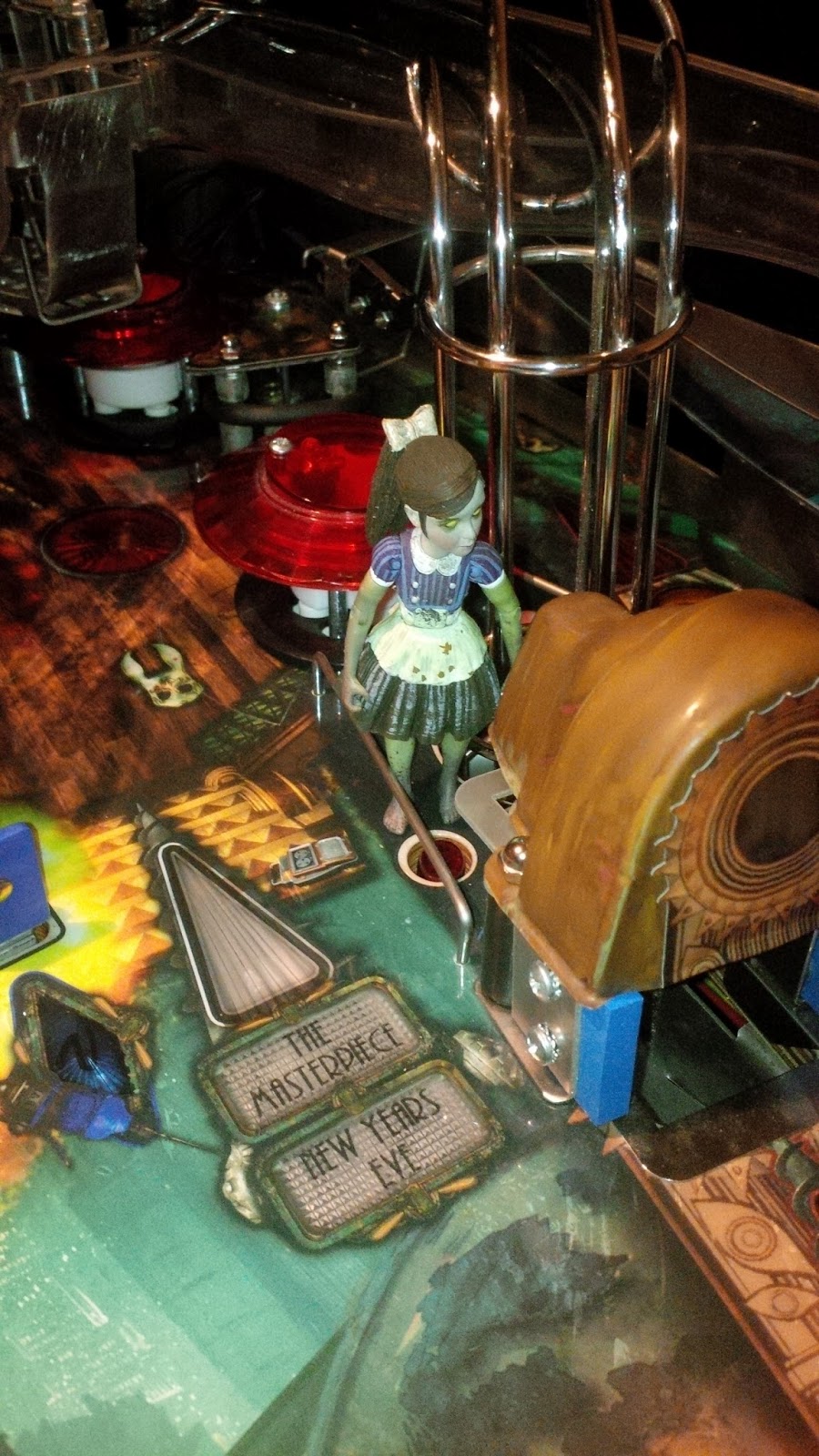 |
| 8) Left position. Looking good, but somewhat blocks the red effect-light for the VUK. |
 |
| 9) Right position. Also pretty nice and brings balance to the playfield. Doesn't look as integrated as the left, thou. |
The "good" little sister has gotten her space at the end of the EVE-hypo, near the left outlane. That space needed a little decoration and this was spot on. The only downside would be the lack of proper lighting at that spot. I'll need to investigate this as soon as the lights are up and running, but worst case scenario is that I'll either cut holes in the playfield plastic for light to shine through or simply point a spotlight at her location.
 |
| 10) The "good" sister with the plastic bracket that holds her in place. |
The current state of the machine. Missing a few details in this picture, such as the little sisters, vent and the VUK, but as a whole it's really starting to take shape now.
 |
| 11) Near finished! Can't wait to put some coins in it! |
Friday, June 7, 2013
Wednesday, June 5, 2013
These boots were made for walking
Well, sort of.
Mr Bubbles has put his feet down and is properly anchored in the ground now.
Before he can swing about, I need to grind a little material of his arm since I managed to insert the servo slightly angled. It won't be visible and won't be a problem, but it's something that needs to be done. Then I need to solder his motor and fix the arm in a removable fashion.
A little tinkering here and there mostly, but still it's something.
It's a swedish holiday and I've got more or less nothing to do, so I'll try to get some soldering on the lights done tomorrow. Would be awesome to have it up and running before the weekend!
The current state of the upper playfield:
Looks more or less the same as before, but this time the parts are actually in place and not just laid out to get a nice picture. Shaping up!
Mr Bubbles has put his feet down and is properly anchored in the ground now.
 |
| 1) Mr B, King Bubbles, Big D... no, that's not it. I'm thinking about ditching the playfield plastic that will be/was going to cover the area around Mr Bubbles. I'm not sure thou, since there's no way for the ball to escape in case it volleys in there... Food for thought! |
Before he can swing about, I need to grind a little material of his arm since I managed to insert the servo slightly angled. It won't be visible and won't be a problem, but it's something that needs to be done. Then I need to solder his motor and fix the arm in a removable fashion.
A little tinkering here and there mostly, but still it's something.
It's a swedish holiday and I've got more or less nothing to do, so I'll try to get some soldering on the lights done tomorrow. Would be awesome to have it up and running before the weekend!
The current state of the upper playfield:
 |
| 2) The upper play area. The cables that are visible will obviously be hidden from view in the final version, but I haven't decided the best way to route them yet. I'm rather picky when it comes to the upper cable routing since I really hate visible cabling! |
Looks more or less the same as before, but this time the parts are actually in place and not just laid out to get a nice picture. Shaping up!
Sunday, June 2, 2013
Do not underestimate the power...
...of moving to a new apartment.
I've basically done nothing on the machine for the past month. :(
Too busy with other stuff (i.e life) and family, but hopefully I'll be back on track soon!
I've basically done nothing on the machine for the past month. :(
Too busy with other stuff (i.e life) and family, but hopefully I'll be back on track soon!
Friday, May 3, 2013
Dot Matrix Disorder
Finally got a good workflow in designing DMD-animations now.
The original plan was to use Flash to create sequences as I've seen a couple of people do on the internet, but the user interface is horrible. Downright awful.
So now I'm back to using proper video editing programs instead which is a much nicer experience!
Maybe it's because I'm used to it - but basically it took me a couple of hours to generate a simple video using Flash compared to just a couple of minutes using video editing. Not to mention the horror of altering something...
I've also got more or less a 100% preview possibility with a DMD-emulation "filter" than I've created, including properly pixelating the image and bit-crunching it. Can't argue with realtime feedback!
Now I'll just have to find a decent VFX library for smoke, explosions and lightning...
Oh, the irony of using high end video editing software, plugins and HD movie material to generate a 128x32 pixel sized 3-bit image sequence...
Thursday, April 25, 2013
Moving out, moving in!
We'll be moving to a new apartment in a couple of days - can't wait!
That of course means less updates for a while, but I hope that's all right since the coming updates will be worth the wait!
That of course means less updates for a while, but I hope that's all right since the coming updates will be worth the wait!
Wednesday, April 17, 2013
Connecting connections!
Just posting a quick update today.
I've started to finalize cabling and replacing too long wires, color coding wires etc. That should help tremendously while debugging and/or servicing the board. Besides this I've started to wire up the servo and motor connections with their custom cables.
I'm also doing an updated version of the I/O layout of the board since the old layout got its walking stick rather quickly. The great thing is that this step is crucial when designing a PCB, so when the time comes it should basically just be a matter of placing the components in the drawing since the pin mapping is already made.
 |
| 1) Near completed motherboard. The tape retaining the lightboard is not the final version. I'll probably use red tape instead... |
Just a few more hours work and the motherboard should be complete!
Unless I've misplaced a wire. Or worse.
Tuesday, April 16, 2013
The power of Jalapeños!
I'm finally finished with the lightboard! <insert fanfare here>
And guess what?
ALL ports are fully functional! <insert epic rock music here>
Let me repeat that -
All ports work, each and every one of them.
That's nothing short of a miracle!
After a couple of months I've finally recreated the "blink" tutorial (...)
As you can see, there's no Chipkit in the image. I usually prototype new classes and boards on the Arduino first, since the Arduino is actually a lot faster during upload and is also separate from the motherboard, which should be handy in case something goes wrong.
Now I'll just have to finish writing the lighting routine so I can hook this guy up to the motherboard!
Awesome!
And guess what?
ALL ports are fully functional! <insert epic rock music here>
Let me repeat that -
All ports work, each and every one of them.
That's nothing short of a miracle!
After a couple of months I've finally recreated the "blink" tutorial (...)
 |
| 1) The finished lightboard up and running! Around 940 solder points later... The MOSFET's are n-channel so I can apply any voltage needed (0-60V @ 30A) for that particular port without affecting the others. |
Now I'll just have to finish writing the lighting routine so I can hook this guy up to the motherboard!
Awesome!
Sunday, April 14, 2013
Another bank bites the dust!
The lightboard is now at 75% completion.
Another solder session and I'll be ready to test it out!
I'm thinking about designing a PCB to replace the motherboard, or simply purchasing either a P-ROC or Ben Heck's custom board. Personally I like Ben's version better, but the P-ROC is verified and used by numerous projects. But my "I can do it"-spirit says that a custom made PCB would indeed be very cool.
It will have to wait for a while - until the current setup breaks that is.
Another solder session and I'll be ready to test it out!
 |
| 1) Solder mess. Should be very interesting to test this. I will most likely need some sort of compartment for this since the cables are pretty fragile and might break when inserting or removing the 50 pin cables from each socket! |
 |
| 2) My session companion. This or Blair's Death Rain chips... *drool* |
I'm thinking about designing a PCB to replace the motherboard, or simply purchasing either a P-ROC or Ben Heck's custom board. Personally I like Ben's version better, but the P-ROC is verified and used by numerous projects. But my "I can do it"-spirit says that a custom made PCB would indeed be very cool.
It will have to wait for a while - until the current setup breaks that is.
Techvolution
It's no surprise that the computer industry is moving forward at lightning speed - but it's astonishing just how much things change over a few years.
I've decided to build a new computer and was happily surfing the net for parts. I decided to see how my old computer's graphics card would measure up to a modern one. Turns out... it doesn't.
It's almost ridiculous...
To be fair -
My current computer wasn't bought to do intense gaming, since I had my Xbox for that. But now the old box is obsolete and the next gen is around the corner (still "next-gen"?!). But I figure I'll return to computer gaming for a while as it also benefits in other ways, such as music production and game creation.
But it's always fun to see how far technology has come!
I've decided to build a new computer and was happily surfing the net for parts. I decided to see how my old computer's graphics card would measure up to a modern one. Turns out... it doesn't.
It's almost ridiculous...
 |
| 1) David and Goliath. |
My current computer wasn't bought to do intense gaming, since I had my Xbox for that. But now the old box is obsolete and the next gen is around the corner (still "next-gen"?!). But I figure I'll return to computer gaming for a while as it also benefits in other ways, such as music production and game creation.
But it's always fun to see how far technology has come!
Saturday, April 13, 2013
I'm back!
Got the new USB-port today and soldered it in place.
And it works!
 |
| 1) USB-port is good to go! |
 |
| 2) The tiny USB-port. The specs say "reflow procedure only". Phuh! |
 |
| 3) Powered up and ready to go! |
Sunday, April 7, 2013
Baby Steps
The last couple of days I got my thumbs out and got to it -
I've removed the motherboard from the machine and tried to fix it.
The removal went easier than expected as I've somehow forgot that I made the board removable as a single piece - despite it being a rather lengthy process of actually removing it.
Once removed, I noticed that two out of five prongs in the USB-connector were broken so at first I simply tried to wiggle the cable in place - which worked. But just as I was going to hot glue the cable in place the remaining prongs broke off as well.
I then figured I'll just replace the USB-port but accidentally broke a circuitboard trace instead. Doh!
But, luckily, after a while on google and the Chipkit-forum, I found out that the one I broke wasn't actually in use for the Chipkit so I'm still good to go. The port is ordered and will hopefully arrive in my mailbox soon. It says "reflow procedure only" but as my friend says - nobody remembers a coward.
Since the work involved removing the board is rather cumbersome I've decided not to reinstall the board until the lightboard is completed, which at the moment it's at 50% complete.
While at it, I took a peek at the broken MOSFET for the left bumper. I couldn't see any immediate problems with it but decided to replace it and the diode on the solenoid itself, should it be the problem.
Hopefully this will keep the left bumper up and running. If not.... then I have no clue what the problem might be. I'll probably use a solid state relay on one of the minor solenoids and use the freed port for the bumper instead.
I've also attached the spinners,spotlights and switches cables now so all the visible switches and lights are looking good. Still the actual connecting left to do - but having shrink wrapped cables with no visible solder joints does a pretty big difference in appearance!
Mr Bubbles has gotten a slight update with a tiny circuitboard for the multi-LED in his helmet, along with the servo now properly installed in his belly.
I've unfortunately decided to back down on Mr B's movement pattern and will let his disco moves become subject to a future mod (but the swinging arm and drill is still present).
I'm thinking it's better to get it up and running first instead of not at all, right?
Took a lot less time to write up the summary than to do the actual work, but that's the way it is!
 |
| 1) The motherboard minus light board. Like Ben Heck says, 'Always build something you can take apart later'. I'm glad I listened, Ben! The observant can see a piece of electrical tape on one of the shift registers, which in this case means a dead shift register. |
The removal went easier than expected as I've somehow forgot that I made the board removable as a single piece - despite it being a rather lengthy process of actually removing it.
Once removed, I noticed that two out of five prongs in the USB-connector were broken so at first I simply tried to wiggle the cable in place - which worked. But just as I was going to hot glue the cable in place the remaining prongs broke off as well.
I then figured I'll just replace the USB-port but accidentally broke a circuitboard trace instead. Doh!
But, luckily, after a while on google and the Chipkit-forum, I found out that the one I broke wasn't actually in use for the Chipkit so I'm still good to go. The port is ordered and will hopefully arrive in my mailbox soon. It says "reflow procedure only" but as my friend says - nobody remembers a coward.
Since the work involved removing the board is rather cumbersome I've decided not to reinstall the board until the lightboard is completed, which at the moment it's at 50% complete.
While at it, I took a peek at the broken MOSFET for the left bumper. I couldn't see any immediate problems with it but decided to replace it and the diode on the solenoid itself, should it be the problem.
Hopefully this will keep the left bumper up and running. If not.... then I have no clue what the problem might be. I'll probably use a solid state relay on one of the minor solenoids and use the freed port for the bumper instead.
 |
| 2) Neat cabling is A to Z. Go the extra mile! Unless it won't be visible. Then you can cheat. |
As for programming, not much has been done since the USB-port is broken, but I've started to look at the profile system I've been planing to do for a while.
Since it's a home game with a rather deep ruleset along with achievements I figure it'll be hard to finish it all in one go - so I'm looking at writing a kind of save game functionality. It will be possible to create and assign profiles for record keeping and competitions etc.
More about this in a later post!
 |
| 3) Early shot of the multi color LED circuit. A downer was that there seem to be a limit in the LED itself so I cannot mix colors by applying voltage on several pins. I'll probably have to emulate the yellow color in software to compensate for this. |
I've unfortunately decided to back down on Mr B's movement pattern and will let his disco moves become subject to a future mod (but the swinging arm and drill is still present).
I'm thinking it's better to get it up and running first instead of not at all, right?
Took a lot less time to write up the summary than to do the actual work, but that's the way it is!
Saturday, March 23, 2013
Rinse, repeat...
"-So, what do you do in your spare time?"
"-I'm mostly sitting hunched over my soldering iron and smelling the fumes."
"-Right... I... should be going now."
Slowly getting there...
I will genuinely be surprised if even half the ports on this board works when I'm finished with it.
Next time - Pay up, Mr!
"-I'm mostly sitting hunched over my soldering iron and smelling the fumes."
"-Right... I... should be going now."
 |
| 1) It just keeps bringing more friends along... |
I will genuinely be surprised if even half the ports on this board works when I'm finished with it.
Next time - Pay up, Mr!
Tuesday, March 19, 2013
Cables...cables everywhere.
Sometimes I really annoy myself, or rather become annoyed by my "I can do this myself"-attitude.
Like the light board for instance - why, oh why, didn't I just order this pre-made on the internet?
What you see on the picture is a gazillion solder points and A QUARTER of the cables needed to complete it. After that, some serious testing and hopefully at least some of them function... Right now I don't remember if I have any light slots to spare, so hopefully they'll all work. I hope.
I thought about both remaking it using a matrix instead or simply design it in CAD and have it manufactured instead. Both things cost money thou, but at the moment I don't really care...
No matter how hard I try, all I see when I look at the board is this...
Like the light board for instance - why, oh why, didn't I just order this pre-made on the internet?
 |
| 1) Satan's lightboard. This is a painful reminder why the invention of circuit boards came to be. |
I thought about both remaking it using a matrix instead or simply design it in CAD and have it manufactured instead. Both things cost money thou, but at the moment I don't really care...
No matter how hard I try, all I see when I look at the board is this...
 |
| Source: http://www.wired.com/beyond_the_beyond/2008/03/ |
Friday, February 22, 2013
Shameless promotion
Thought I'd just drop a few lines about my other passion in life - my band.
We're called Chugger.
What we play could be called locomotive metal due to its unstoppable, undeniable and raw nature.
Check us out at our official homepage or on facebook!
Here's our latest video for our demo version of "Bleed".
Viewer discretion is advised.
We're called Chugger.
What we play could be called locomotive metal due to its unstoppable, undeniable and raw nature.
Check us out at our official homepage or on facebook!
Here's our latest video for our demo version of "Bleed".
Viewer discretion is advised.
Sunday, February 17, 2013
Preliminary sketches
So this is the current state of the CNC-machine:
Not too impressive, but I'd rather have it as good as possible before actually making it.
Note that the rails for this design is based on 30mm width/height, but hopefully I'll find L-profiles of a smaller size so the overall design will be slimmer and the cut area slightly larger.
Thoughts?
 |
| 1) Front view. I won't go into a lot of details yet, but it will be chain driven X/Y-wise and a lead screw for the Z-axis. I hope to reduce the carriage width by around 5-10 cm in the final version. |
 |
| 2) Side view. Hopefully I've gotten most of the weight centered to avoid wobbling. The expected cut length is around 117.5 cm, which is slightly larger than a regular pinball playfield. Larger pieces can be cut with a little manual repositioning of the carriage and resetting of the zero-position in software, but I do believe this should be sufficient to start with. |
Note that the rails for this design is based on 30mm width/height, but hopefully I'll find L-profiles of a smaller size so the overall design will be slimmer and the cut area slightly larger.
Thoughts?
Monday, February 11, 2013
It moves like Jagger!
Got the motors running just now!
I had quite a struggle getting them to run due to a) pretty crappy chinese documentation and b) I missed the fact that each motor had it's own enable line that must be held high during operation.
But they seem to be working fine and are actually a lot less noisy than I expected them to be.
Hopefully they'll have enough juice to drive my rig...
Now I'll just need to get my hands on the rest of the parts and start building!
I had quite a struggle getting them to run due to a) pretty crappy chinese documentation and b) I missed the fact that each motor had it's own enable line that must be held high during operation.
But they seem to be working fine and are actually a lot less noisy than I expected them to be.
Hopefully they'll have enough juice to drive my rig...
 |
| 1) Driverboard, power supply and X,Y,Z-stepper motors. In case you're wondering why there are unplugged cables everywhere - the motors are bi-polar 6-cable versions and only 4 are required. They will be cut appropriately during assembling... |
Virtual movement!
Received most of my parts for the CNC machine now - all that's missing is a few bearings, an aluminum rod and the wood for the frame itself.
I was originally planing on connecting the CNC-router driver to my Mac, but as it turns out CNC-driver boards are only using the parallel port. This is due to the unreliability of the USB protocol/port and the fact that there's a very low number of I/O pins compared to LPT-ports.
Luckily, my father had an old laptop that I could use instead. Really ancient hardware, but since the Mach3 software is designed for very low end computers it works just fine!
Behold!
The vast amount of configurable things in this software is staggering. Hopefully I won't have to trim each one of them since I'm going for sub-millimeter accuracy - not sub-nanometer...
Now I'll just need to get the power supply and motors connected!
I was originally planing on connecting the CNC-router driver to my Mac, but as it turns out CNC-driver boards are only using the parallel port. This is due to the unreliability of the USB protocol/port and the fact that there's a very low number of I/O pins compared to LPT-ports.
Luckily, my father had an old laptop that I could use instead. Really ancient hardware, but since the Mach3 software is designed for very low end computers it works just fine!
Behold!
 |
| 1) CNC-software Mach3. Currently "dry-running" the example "roadrunner.tap" file. |
Now I'll just need to get the power supply and motors connected!
Wednesday, January 23, 2013
Cut my life, into pieces...
Hi ya'll.
While building up the willpower needed to repair the pinball machine (both the left bumper and Chipkit) I've got sidetracked somewhat -
I'm building a CNC-machine.
Wait, what?
It actually makes sense thou.
A lot of times I've found myself thinking "if only I had this" or "if only I had that" and quite frankly, it would seriously decrease the time needed to prototype and produce things. Among the first things to be processed would be custom solenoid holders for the pinball machine. I'm planing on making a functional prototype out of MDF board and then use that prototype to cut out a proper machine out of heavy duty wood (or aluminum). The size of the CNC will be large enough to allow a full scale pinball machine to be cut out (one part at a time obviously), but will not be limited to that.
The design is flexible enough to grow in all axises in case it really kicks of and I need to move it to a separate location. But looking around in the apartment there's few things larger than a pinball machine, so I'll most likely be able to cut out any piece of furniture, toy or thingamajig I can think of - especially since the Y-axis is extendable indefinitely.
Another cool thing is that when the mechanic X,Y,Z axis are in place, the actual device can easily be changed into a 3D-printer, pick&place or a laser cutter etc. The driver board I've ordered alongside the motors is already prepared for powering external devices, and should the need arise, driver boards for additional axises can be purchased cheaply on Ebay.
After that, well...I'll be taking orders on stuff to fabricate!
(I'm actually planning on selling both blueprints and actual DIY CNC-machines when done...)
Sunday, January 20, 2013
Major Setback, or Sergeant Crap.
I left the USB-cable dangling outside the pinball machine, still connected to the Chipkit MCU.
Then my daughter found it.
And pulled it.
Now I've got to get myself a new Chipkit.
Then my daughter found it.
And pulled it.
Now I've got to get myself a new Chipkit.
Thursday, January 10, 2013
Parts of me...
Thought I'd post a couple of pictures on some of the playfield parts.
 |
| 1) The 'Advance Clock' lane of the upper level. A passage feeds the ball from the top level to the right orbit. |
 |
| 2) The custom habitrail from the upperlevel to the right inlane. It seem to be held up by magic, floating in mid-air... |
Monday, January 7, 2013
Walking backwards into the future...
I have (finally) started to wire up the lights and switches... About time, if I may say so.
The machine is now autonomous in terms of starting a game, loading balls, autolaunching, ball search, multiball etc, so an actual game can be played. Without any rules.
I've begun thinking about the rules and have a basic framework set up, but nothing's programmed yet.
Due to some unfortunate incidents it took a little longer than it should've. But we'll get to that later.
All right,
As I wrote before, the machine is now autonomous.
When inserting a credit and pressing start, or simply pressing start during free play, a game is started.
The game then checks if there's any ball in the shooter lane and launches one in case there's none.
During the initial ball launch a switch hit other than the shooter lane switch is required to properly start the game. In case the game is started and a ball magically falls down the shooter lane, that ball is automatically kicked back into play.
When the drain switch is hit, the bonus sequence starts and the ball is kicked back into the ball-through.
Then another ball is ejected to the shooter lane and the next ball is played. In case there's no game running the drain simply kicks the balls out of the way. This is also the way balls are being loaded into the game after maintenance etc.
In case no switch is hit for a 25 second period a ball search is initiated. All relevant solenoids (and the motorized target bank) are being pulsed three times during seven second windows, stopping at any time if any switch is being hit. In case no switch has been hit after a total of 46 seconds the ball is considered lost and a new ball is autolaunched (or simply ejected, in case that's the preferred option chosen). Should the lost ball somehow return to play, both balls will be lost when either of them drains.
I've experimented with multiball and thought of a simple system -
A total number of balls are being requested by the game and in case there's less than that number of balls, a new balls is autolaunched into play. Great care has been taken in designing it, so that it's non-blocking and allowing for easy gameplay design. In case a ball is drained and the "shoot again" timer is still active, the drained ball doesn't decrement the total ball count requested, causing a new ball to be launched into play.
It's simple and very elegant i.m.h.o.
I will combine this with an additional ball counter so that the game hopefully never looses track of any balls. I need this since it's a 4-ball multiball game and there's a physical lock involved. In case the lock is partly filled and another multiball is launched, one or more balls will be released from the lock. During single ball gameplay and the lock is missing balls, the locking could be restored until the same amount of balls has been locked as before the other multiball - or simply become virtual locks instead.
( Actually, I have a mode that allows you to collect any number of balls to use in multiball, sort of like an unlimited ball save timer until the last collected ball has been drained )
 |
| 1) Wires, wires, wires. And that's not even half of them. The power cables are connected in a network with multiple contact points so that the power always (as in - hopefully) get routed to most switches and lights in case a connection breaks somewhere. I bless the testing mode I've developed which has already helped me tremendously while troubleshooting. |
The machine is now autonomous in terms of starting a game, loading balls, autolaunching, ball search, multiball etc, so an actual game can be played. Without any rules.
I've begun thinking about the rules and have a basic framework set up, but nothing's programmed yet.
Due to some unfortunate incidents it took a little longer than it should've. But we'll get to that later.
All right,
As I wrote before, the machine is now autonomous.
When inserting a credit and pressing start, or simply pressing start during free play, a game is started.
The game then checks if there's any ball in the shooter lane and launches one in case there's none.
During the initial ball launch a switch hit other than the shooter lane switch is required to properly start the game. In case the game is started and a ball magically falls down the shooter lane, that ball is automatically kicked back into play.
When the drain switch is hit, the bonus sequence starts and the ball is kicked back into the ball-through.
Then another ball is ejected to the shooter lane and the next ball is played. In case there's no game running the drain simply kicks the balls out of the way. This is also the way balls are being loaded into the game after maintenance etc.
In case no switch is hit for a 25 second period a ball search is initiated. All relevant solenoids (and the motorized target bank) are being pulsed three times during seven second windows, stopping at any time if any switch is being hit. In case no switch has been hit after a total of 46 seconds the ball is considered lost and a new ball is autolaunched (or simply ejected, in case that's the preferred option chosen). Should the lost ball somehow return to play, both balls will be lost when either of them drains.
I've experimented with multiball and thought of a simple system -
A total number of balls are being requested by the game and in case there's less than that number of balls, a new balls is autolaunched into play. Great care has been taken in designing it, so that it's non-blocking and allowing for easy gameplay design. In case a ball is drained and the "shoot again" timer is still active, the drained ball doesn't decrement the total ball count requested, causing a new ball to be launched into play.
It's simple and very elegant i.m.h.o.
I will combine this with an additional ball counter so that the game hopefully never looses track of any balls. I need this since it's a 4-ball multiball game and there's a physical lock involved. In case the lock is partly filled and another multiball is launched, one or more balls will be released from the lock. During single ball gameplay and the lock is missing balls, the locking could be restored until the same amount of balls has been locked as before the other multiball - or simply become virtual locks instead.
( Actually, I have a mode that allows you to collect any number of balls to use in multiball, sort of like an unlimited ball save timer until the last collected ball has been drained )
The slingshots, VUK's, saucer and bumpers are wired up as well.
But when testing I noticed that something isn't right with the new power-driver board I order last.
For some reason the bumper rigged to that card stopped working - and after a little troubleshooting (to be very modest) I replaced the MOSFET with a spare one and it started working again.
Unfortunately - most of the switches on the right side of the board stopped working. It turns out the shift register that handled those 8 switches had been fried. Once that was fixed everything was good.
For a while.
Then the very same bumper broke down again. This time without killing any switches however, to my great joy. The MOSFET is probably busted thou. The card is a pain to remove so I'll probably won't be doing anything more on it until I need it.
I had the same problem with the magnet a while ago, so I'm thinking the diode might be broken on the bumper and causing a reversed voltage spike to fry the MOSFET, perhaps? In any case - that's five broken MOSFET's on the same card. None of the other cards has had any troubles at all, so I'm leaving my options open on this one.
Subscribe to:
Posts (Atom)